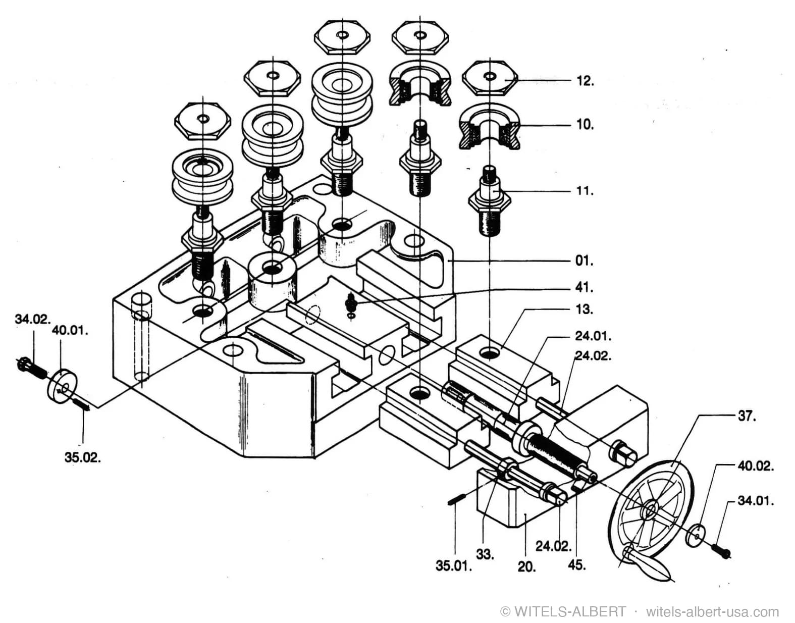
Rather than describe the straightener as a tool and its function, we want to draw attention here to its precise and modular design.
The "A" parts of a straightener's design, i.e. its basic load-bearing elements, are adapted in size to the number of rolls to be accommodated and serve as mounts for the "B" parts such as rails, grooved blocks, threaded bolts, pins and other standard parts.
The final block of this modular design are the straightening rolls. They are also the parts exposed to the greatest wear.
An approach based on the ideas of environmental management gives rise to a product and production engineering of outstanding accuracy, impressive ruggedness and durability, and unique operability and results.
Adapted from "We do it straight" — Wire Straightening, p. 159 (ISBN 3-00-005897-4).